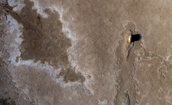
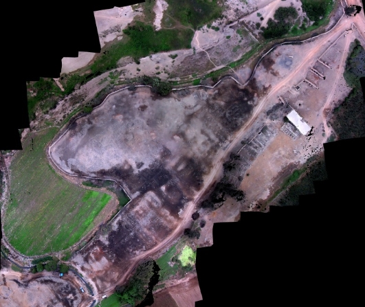
I co-authored a couple of papers where my role in the research was creating 3d models using photogrammetry with kite aerial photography (Bibi et al. 2012; Benfer et al. 2014), but it has been a while since I fired up a model. I’m now knocking the rust off old skills and learning new software. My prior efforts were focused on whole sites, excavation units, and profiles (Figure 1). Now I’m looking at building models of artifacts, and that means I need to photograph the entire object. Doing this often involves capturing up and down images, building models in chunks, aligning those chunks, and merging them. It’s been a bit since I’ve done any of this. However, that last part isn’t something I looked into much even before. I started tinkering with Metashape 2.0.2.
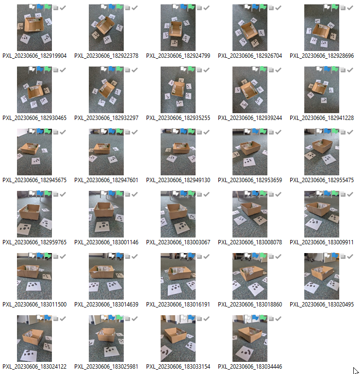
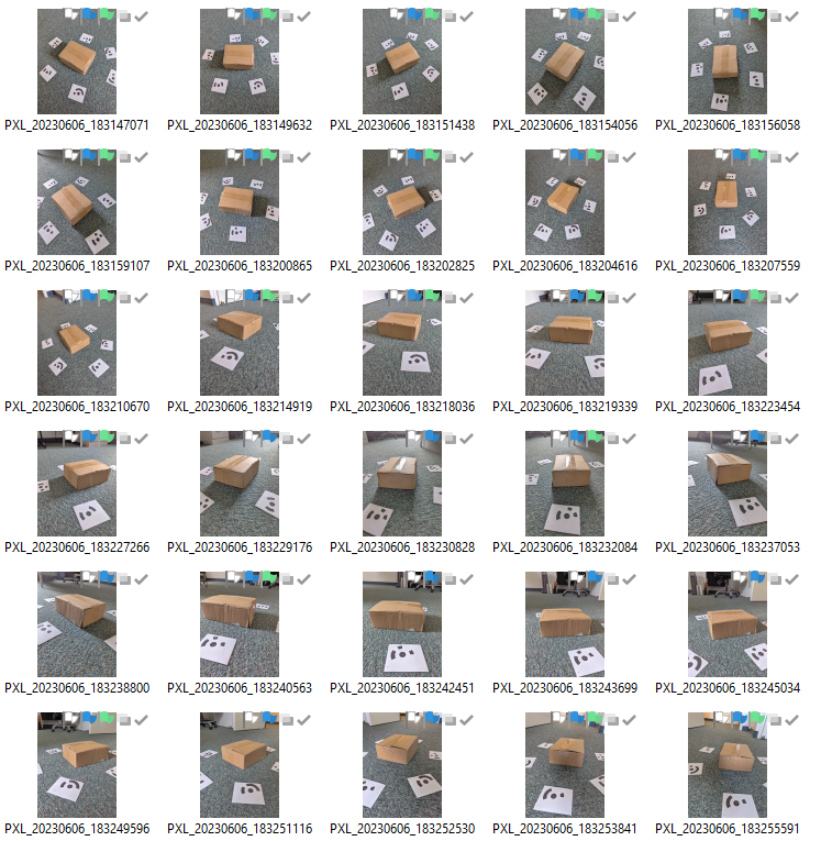
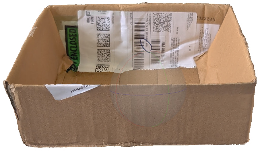
For hammering out this workflow I used a small box laying around as the object to reconstruct (Figure 2). It is matte and should reconstruct well. It is also relatively undifferentiated on the cardboard panels, and the object is thin. I didn’t so anything special for lighting, and I was working around my desk in an awkward way.
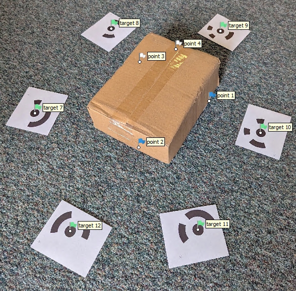
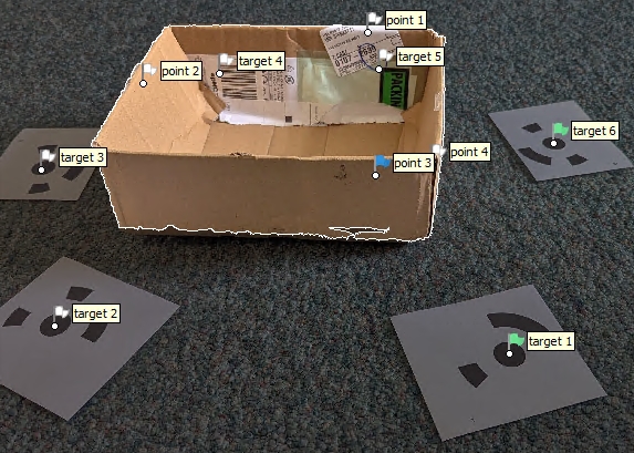
I laid out two sets of coded targets, one for the images of the top the box (Figure 2 (a)) and another for the pictures of the bottom (Figure 2 (b)). At the alignment and merge stage of the process, it is important to have unique targets for the two scenes. Also, for each set of coded targets I placed two of them at a known measured distance. This is necessary to set the scale. I didn’t measure a set of test distances, but doing so is smart–next time. It also would have been good practice to have a set of scales on both sides of the object; this applies to both the top and bottom image sets.
No effort was made to get soft lighting, and portions of the box are in shadow. To make the photographs, I just used my Pixel 6 cell phone and left the settings on automatic. I’m pretty sure there is a ton of processing that goes on under the hood before it comes off the phone.
General Process for One Half
- Right click in the workspace area and select
Add Chunk - Name the chunk
- Add photos
- Detect Markers
- Align Photos
- Resize the area
- Create scale bar
- Build mesh
- Build texture
- Remove unwanted pieces
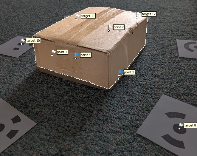
After completing both halves, the aim is to merge the chunks into a single model that shows all sides of the object–in this case a box (Figure 3).
Discussion of Steps to Build One Half
These procedures are done for the top and the bottom image collections (Figure 2). Below I lay out the procedures once assuming that it will be run twice before proceeding to merge and alignment of the two halves.
- Place targets around object and accurately measure the distance between at least two of the targets
- This measurement will be required later for properly setting the scale of the model.
- To ensure accuracy throughout the model, consider measuring the distance between more than two points.
- Capture photographs
- Don’t use a zoom
- Use consistent white balance
Preprocessing
- Preprocess in Raw Therapee using highlights and shadows tool. Note this process is recommended by some users, but is optional and may not necessarily give better results.
Open Raw Therapee and browse to the folder that contains the images for the project. I keep images for top and bottom chunks in separate directories so this process needs to be done twice.
Having browsed to the directory containing the image collection, double click one of the images to open it in Raw Therapee
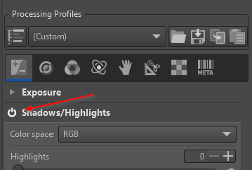
With the image open, activate the
Shadows and Highlightstool by clicking theOnbutton (Figure 4).
Adjust highlights to bring down any over exposed areas
Adjust shadows to raise any heavily shaded zones
Adjust both controls with an eye towards revealing the greatest amount of information in the photograph. It is a tradeoff.
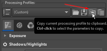
Once the settings are established for one image, copy them by clicking the
Copybutton (Figure 5).
With the settings copied, then spot check the effect of those settings on other individual images by double clicking it and then clicking the
PastebuttonIf the settings work on various images, then select all of the images in the collection by right clicking and Select All
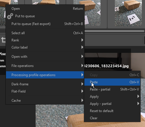
With the images selected, right click again and select
Processing profile operations > Paste. Note I did not have success withCrtl + Vbut it does work with right click (Figure 6).
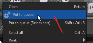
- Once applied, with all of the images still selected, right click again and select
Put to queue(Figure 7)
With the files queued, click on the queue panel on the right side of the interface.
Select a folder to save the images into and select the desired file format options. I save files to a folder named
preprocessed, I set the JPEG quality to 100%, and the Subsampling toBest qualityWith those parameters set, click the switch to start the process. Once finished, check the results to confirm preprocessing generated desired results (Figure 8)

Align Cameras and Build Model
- Open Metashape and Add Photos
Workflow > Add Photos
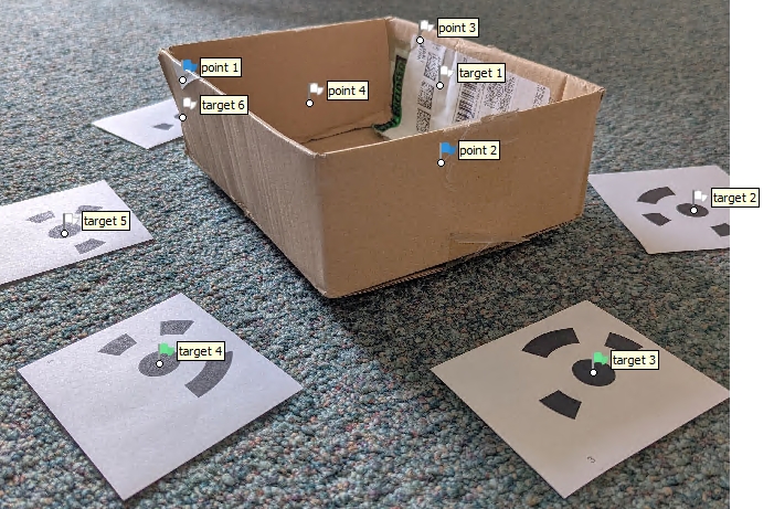
- Detect Coded Targets
Tools > Markers > Detect Markers- Open some of the photos to determine that the markers are properly identified (Figure 9).
- Optional: apply masks to reduce processing time and to make a cleaner initial model.
- Masks can be imported from a mask file or from a model. If the mask is created from a file, then it can be applied early in the process. If imported from the model, the masks are imported after an initial model reconstruction.
- Mask from file works best with background removal with a single object in a scene.
- In this workflow, masks are imported from the model (Figure 10).
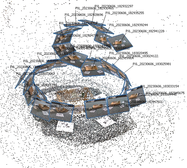
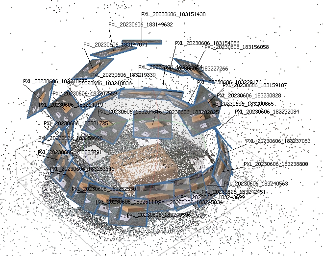
- Align Photos. If there are a large number of images use
Generic Preselection.- Check alignment by clicking the
Show Camerasbutton in the top ribbon (Figure 11).
- Check alignment by clicking the
Agisoft recommends against using Guided Image Matching and Adaptive Camera Model.
- Resize the Region to focus only on the object to be reconstructed
- Create Scale Bar and set Reference Distance
- Left click two markers holding the
crtlkey. - Right click in the model view or on one of the selected markers and select
Create Scale Bar - Enter the distance between the markers.
- Repeat for each set of markers with a known distance.
- Once complete, click the
Updatebutton in theReferencepane. - Then
Rotate Objectto properly set the orientation.
- Left click two markers holding the
- Build Mesh
-
Workflow > Build Mesh. In this case, I opted to directly build the mesh based on Depth maps with the Surface type as Arbitrary (3D). - If a point cloud result is needed then select
Workflow > Build Point Cloudat this step. For site, excavation, and profiles I generally built dense point clouds and meshes from these. For mapping I would often use Surface type height field (2.5D). - It is also possible to generate points from a mesh using
Tools > Point Cloud > Samplethis will sample points from the mesh model.
-
- Build Texture
Workflow > Build Texture
- Remove unwanted pieces of the mesh
- Use the lasso tool
- To avoid deleting markers during the trimming process, make sure that
Show Markersis toggled off
At this point, the top portion is complete and ready to align and merge. The bottom portion is processed in the same way as the top. What follows in the next section is an abbreviated accounting of the previous steps.
Merge Top and Bottom Chunks
Merging chunks strikes me as a bit of an art form. The following workflow was established by trial and error. There may be better ways of doing this.
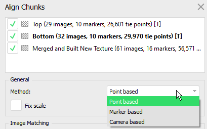
As of 2.0.2, Metashape offers three alignment methods (Figure 12).
-
Point Based: matches points across all chunks. This method does not require the creation of manual markers. However, the calculation can take several minutes. With the box image collection alignment was poor, and may have to do with the nature of the object, uncontrolled camera angles, and poor lighting.
-
Marker Based: matches manually placed markers. This method requires at least three points. When the models are in extremely different coordinate spaces, it can be cumbersome to identify common points. I found that using a point based alignment can be helpful in bringing two models together in the same general space. Once generally aligned, create manual markers, and perform the final alignment. -
Camera Based: aligns based on estimated camera locations. The manual notes that corresponding cameras should have the same label. I have not used this method.
Alignment Summary: Start with point based to get things close. Then use the move and rotate object tool to get both chunks in a place where it is easy to create markers. Once markers are created, realign the chunks using the marker method. Trim any newly identified excess and then merge the chunks.
Going through the two step alignment process, I asked myself the question: is it possible to manually move the two models near by without using Point Based alignment? My initial answer is no because in my experience models are often so far apart in coordinate space that one can’t see models from the two chunks at the same time until there is some initial alignment. The point based alignment helps with this initial proximate placement.
-
Workflow > Align Chunks- With the box model, I started with
Point Basedto get a near alignment. Then with the two models positioned next to one another, I created four manual markers and did a Marker Based chunk alignment. This worked well. - With the initial
Point Basedalignment complete I used theMove ObjectandRotate Objecttools to position the top and bottom models where I could more easily see to create manual markers. - Once suitably positioned, toggle back and forth between the two models to create the manual markers.
- Manual markers are created by positioning the cursor on the proper location on the model, right clicking and selecting
Add Marker. This creates a new marker on the active model. Corresponding markers must be made on each model to align. This is why it is necessary to toggle back and forth between the two models. - Once at least three or markers are made on each chunk’s model, then align the chunks based on markers.
- Once the alignment is suitable, then perform any additional trimming that is required, and merge the chunks.
- Once aligned, I did quite a bit of additional trimming before merging. With the chunks aligned, it was possible to see additional new areas that required removal.
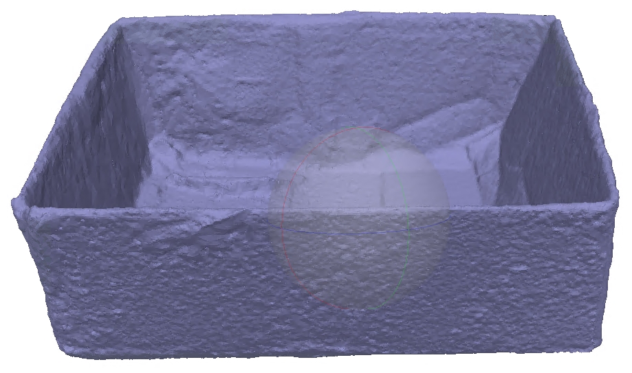
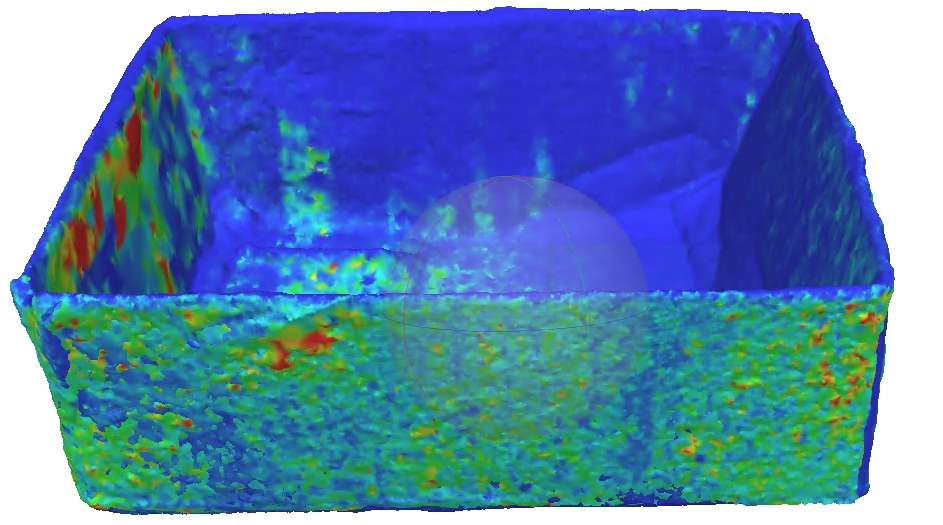
- Looking at the Confidence shading of the models during the merge process can help guide cropping decisions (Figure 13). If there is a decision to make, we obviously prefer to keep high confidence areas. If one model has high confidence on the region and the other model has exceptionally low confidence then it clearly makes sense to crop the low confidence part of the second chunk.
- Once alignment is satisfactory, it is time to merge the models:
Workflow > Merge Chunks. When I merged the models, I included all of the assets. The merged model looked good. However, I wanted to see if I could improve the texture. - I rebuilt the texture increasing it from 8192 to 10000 pixels.
- From here, we have a scaled model ready for export.
- With the box model, I started with


Useul Links
-
Photogrammetry tutorial 11: How to handle a project in Agisoft Metashape
- Exclude stationary tie points is useful with turntable shooting as it instructs Metashape to ignore tie points that do not move between images. According to the author, this is kept checked at all times.
- Copy chunks at key stages in the process, that way if there is an error one can simply go back to the prior stage.
- Optimizing point cloud and alignment is a key step, but is not listed under workflow.
-
Model > Gradual Selection. Selection theReconstruction Uncertaintyoption. The author clicks in the field and types10. This will select low certainty points, delete them. This removes tie points that have low likelihood of being correctly located. It should remove the floating points and leave a pretty clean model. If it removes a bunch of points in the model, then go back to the prior chunk. - Next Optimize the alignment of cameras based just on the higher certainty points. Do this by clicking on the update icon–it looks like a wand.
- Choose
Adaptive Camera Model Fitting. - Select
Gradual Selectionagain and tickReprojection Error. The author selects10and deletes the selected points.
-
- Photogrammetry tutorial 12: my workflow for Agisoft Metashape as a diagram
- Agisoft Forum posts
- Merging different chunks flawlessly? (2015-01-22)
- Best practices for handling 30,000 + images (2017-02-24)
- Technical: Optimisation of Merged Chunks (2017-03-13)
References
Citation
@online{craig2023,
  author = {Craig, Nathan},
  title = {Knocking the {Rust} {Off} {Metashape} {Workflow:} {Merging}
    {Model} {Chunks}},
  date = {2023-06-08},
  url = {https://ncraig.netlify.app/posts/2023-06-08-metashape-workflow/index.html},
  langid = {en}
}