Introduction
In developing methods to construct 3D models of archaeological perishables at the UM, I looked for an object that would represent similar reconstruction problems. The fiber perishables have lots of small pieces, often knotted, or interwoven. For the experimental object, I chose a Devil’s Claw (Proboscidea parviflora) (Figure 1) bundle (Figure 2) that was sitting on a shelf in the museum.

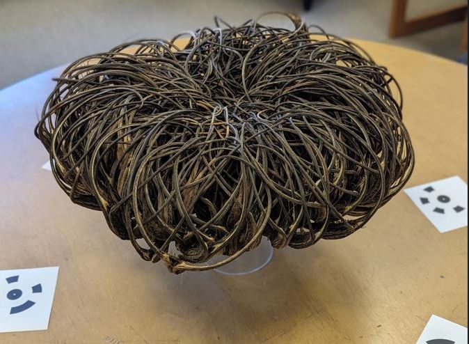
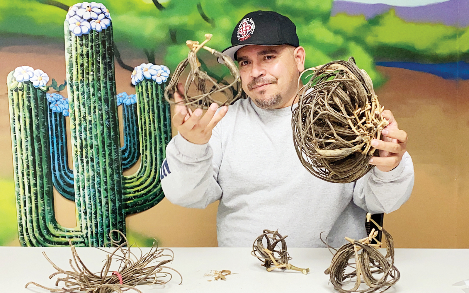
Devil’s Claw is particularly important to the O’odham people who use it for basketry (Figure 3 and Figure 4). Mature and dry pods have long fibers that are excellent for basketry. Young pods (Figure 1) harvested before they harden can be cooked and eaten.

Methods
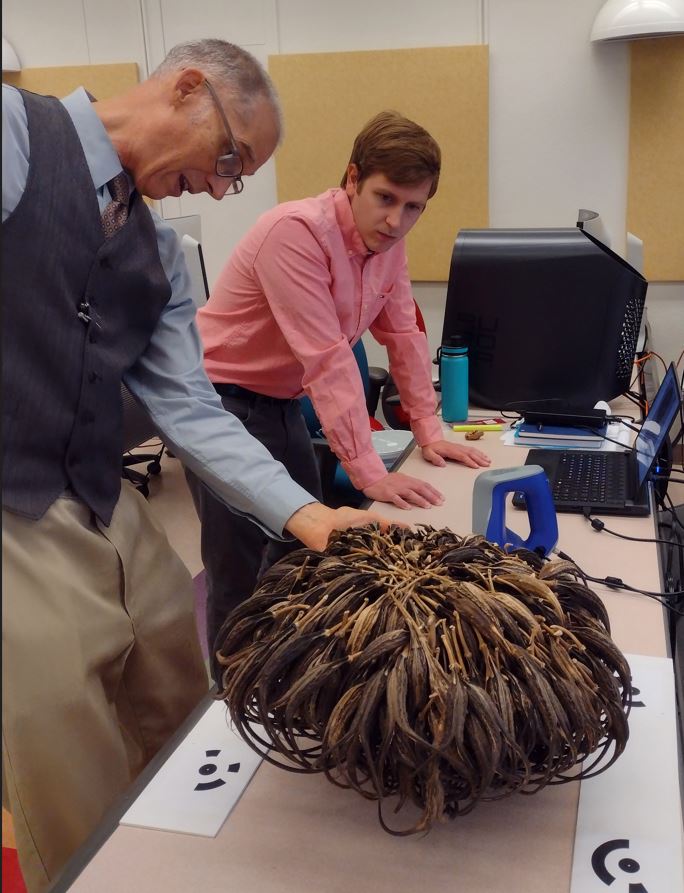
So far, I have two reconstructions of the Devil’s Claw bundle. First I used photogrammetry to build a two part (top and bottom) model that I merged together (Figure 6). I photographed the object with a Google Pixel 6 Pro cell phone and processed the data using Agisoft Metashape. Second, with help from Nathan Camp I used the NMSU Library’s Emerging Technologies Learning Lab laser scanner (Figure 5) to build a reconstruction of the bundle (Figure 7). The library has two Arctec scanners: Leo for large objects and a Space Spider for small objects. I used the ArcTec Space Spider. We actually tried the Leo just to see. It could capture the bottom of the object where the pods are larger, but it could not reconstruct the top of the bundle with all of the little pieces. The Space Spider was able to reconstruct the entire bundle.
Results
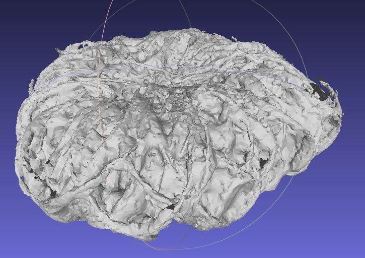
Both the photogrammetry and Space Spider laser scanned results are shown below.
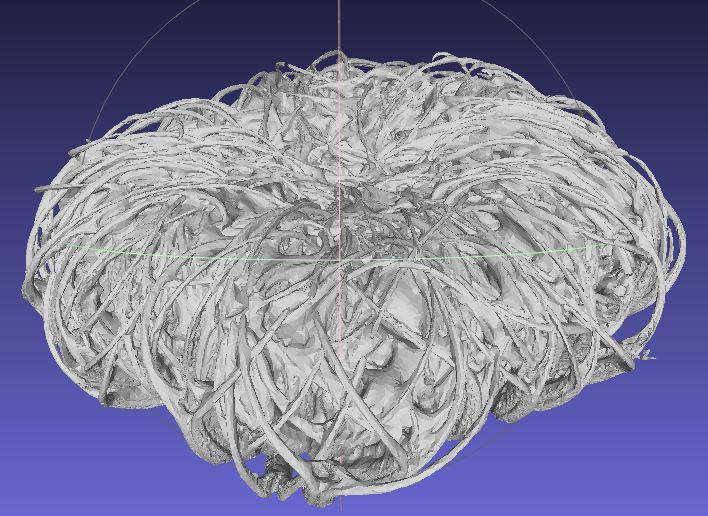
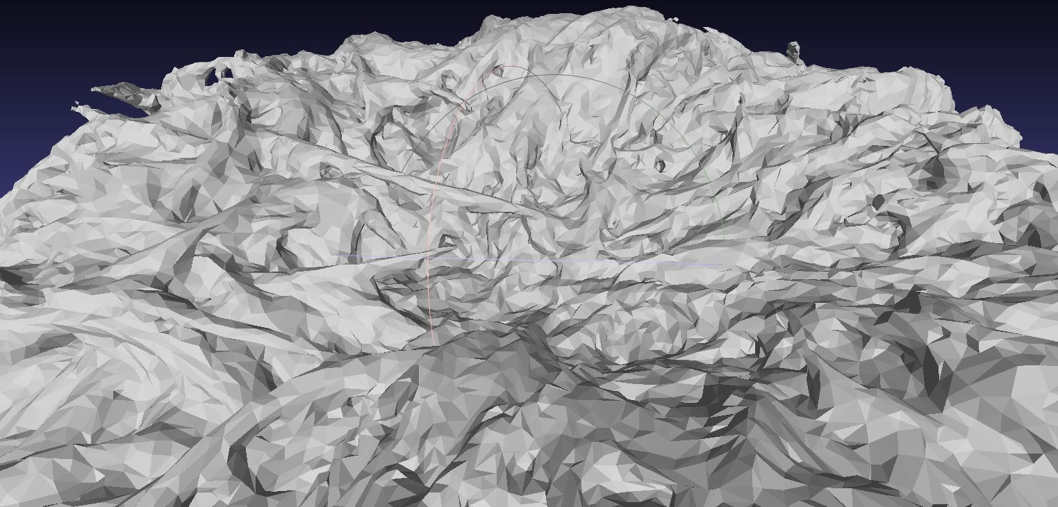
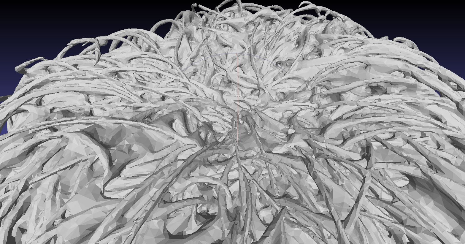
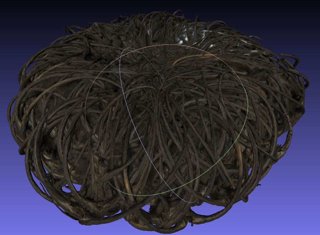
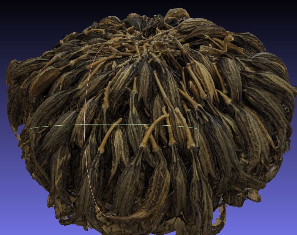
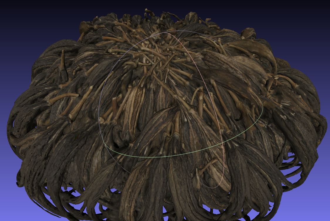
So far, I’ve just made visual comparisons using MeshLab (Figure 8) and visitors can explore the models online via SketchFab. Meshlab has some tools for comparing meshes, but I haven’t looked into those functions just yet. The photogrammetry model’s geometry (Figures 8 (a) and 8 (c)) is not as detailed as the laser scanned model (Figures 8 (b) and 8 (d)). The laser scanned model shows much more of the 3D detail of the original object.
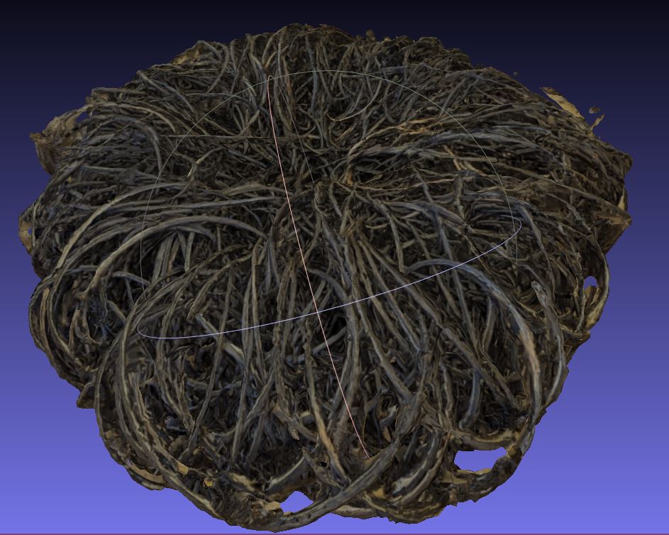
While the scanner provided superior geometry, initial inspections suggest that photogrammetry produced a finer texture file (Figure 9). Details and color changes are more visible in the photogrammetry texture (Figures 9 (a) and 9 (c)) than they are in the texture generated by laser scanning (Figures 9 (b) and 9 (d)).
Concluding Thoughts On a Work In Progress
In terms of building a reconstruction, the laser scanner provides results that are far superior to what I am able to generate so far with photogrammetry. However, the texture file of the photogrammetry object seems a little better than the model texture produced by the laser scanner. I’d like to figure out a way to get the high resolution geometry of the laser scanner with the model texture quality obtained from photogrammetry. Next steps involve looking at the scanner documentation to see what options are available. It looks like ArcTec Studio enables the application of high resolution textures to models using photographs. However, it appears that the camera’s viewing geometry must be the same geometry as the scanner.
General
- When working in MeshLab, sometimes textures do not properly load on import. Fortunately, there is a workaround. The following command reconnects a texture with a model
Filters -> Texture -> Set Texture -> Texture file "TEXTURE_FILE_FROM_CURRENT_DIRECTORY.png"-> Apply
Photogrammetry
- Good strong lighting is necessary to reconstruct recessed areas of the object. This is particularly important with highly textured fibrous objects. The lighting should be diffuse but bright.
- Given that the object is complex but relatively undifferentiated, during the alignment and merging, it was difficult to match the top and bottom chunks. Automated alignment doesn’t work well, and I had to do quite a bit of tinkering to manually identify the correct tie points. However, with a few common points, the alignment processed quickly.
- To get the model small enough to load onto SketchFab, it was necessary to apply some decimation and reduce the size of the texture. It will be important to look into the best methods for reducing model size while retaining detail.
- I didn’t have good luck using AgiSoft’s internal export to SketchFab function. However, manually exporting the model and uploading to SketchFab worked well.
Laser Scanning
- Use a good carousel. The scanner’s stock carousel could not support something with the weight of the devil’s claw bundle. I had to purchase a third party carousel.
- If using a third party carousel, make sure one can control the speed of rotation. The scanner requires a slow carousel.
- When working with really complex objects on a third party carousel, begin by scanning the object stationary in order to construct a framework for the scanner to stay oriented. Once a framework is established by scanning stationary, then begin turning the carousel as slowly as possible.
Citation
@online{craig2023,
  author = {Craig, Nathan},
  title = {3D {Model} {Comparisons}},
  date = {2023-08-23},
  url = {https://ncraig.netlify.app/posts/2023-08-23-3d-model-comparison/index.html},
  langid = {en},
  abstract = {This post compares 3D models built with photogrammetry and
    a laser scanner. The laser scanner produced a superior geometric
    reconstruction but photogrammetry rendered a better texture. Next
    steps involve figuring out how to either combine the best of both
    methods or get a better photo texture from the laser scanner.}
}